Lab 5: Interrupts
Introduction
In this lab, I used an MCU to determine the speed of a motor by reading from a quadrature encoder using interrupts.
Design and Testing Methodology
Design Methodology
This design interrupts to detect pulses from the encoder and calculate the veolcity and direction the motor is spinning in. For both interrupts, rising and falling edge triggers are enabled to achieve the highest resolution measuremnt. Finally, the speed and direction is displayed using fprintf() in units of rev/s at a rate of 2 Hz.
As far as hardware goes, the design uses a 25GA-370 DC Motor and a power supply to adjust the speed.
Testing Methodology
Testing this design was done via hardware verification. The motor was connected to the MCU, and I ensured an accurate velocity measurement was being displayed on the debugging window.
Technical Documentation:
The source code for the project can be found in the associated GitHub repository.
Schematic
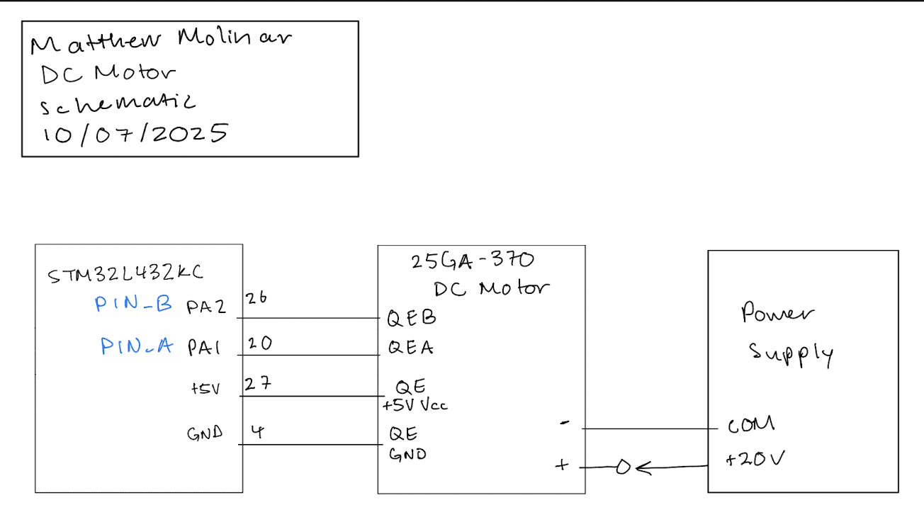 (Figure 1: Schematic of physical layout)
Figure 1 shows the physical layout of the design. The MCU was connected to a 25GA-370 DC Motor, which was also powered with an external power supply.
Flowchart
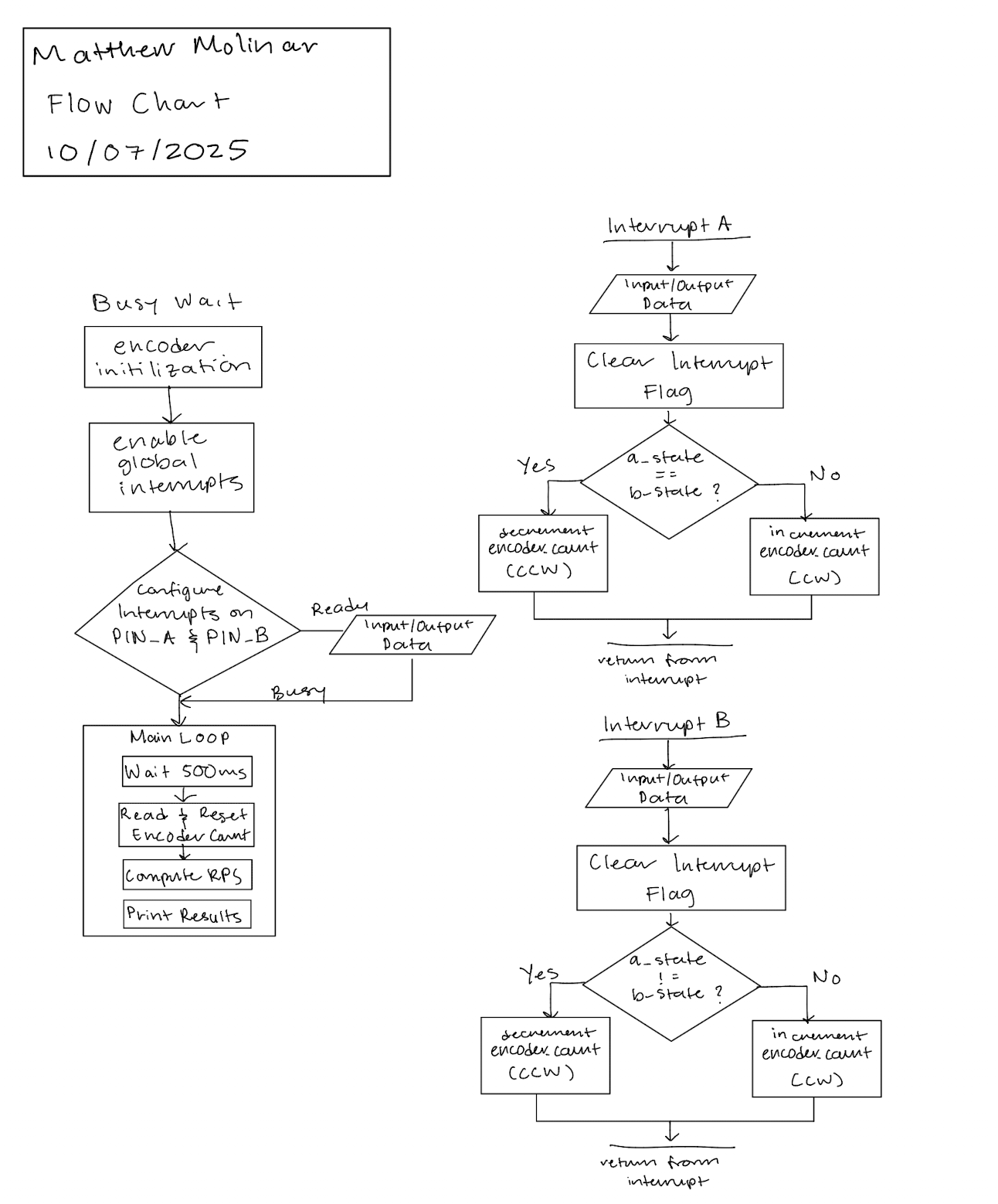 (Figure 2: Interrupt Flowchart)
Figure 2 shows each interrupt and the main loop that is executed.
Measured Speed vs. True Motor Speed
First, I counted the number of pulses and used the following equation to find speed in terms of revolutions per second. Here, count refers to the pulse count and time referes to the time in ms. I was using a display rate of 2 Hz, so time was 500 ms.
\[ rps = \frac{\text{count} \times \left(\frac{1000}{\text{time}}\right)}{4 \times 408} \]
To find the true motor speed, I plugged one of the GPIO pins to an oscilloscope and measured the period of a pulse. Then I used the following eqaution to calculate speed in terms of revolutions per second. \[ rps = \frac{1}{period \times 408} \]
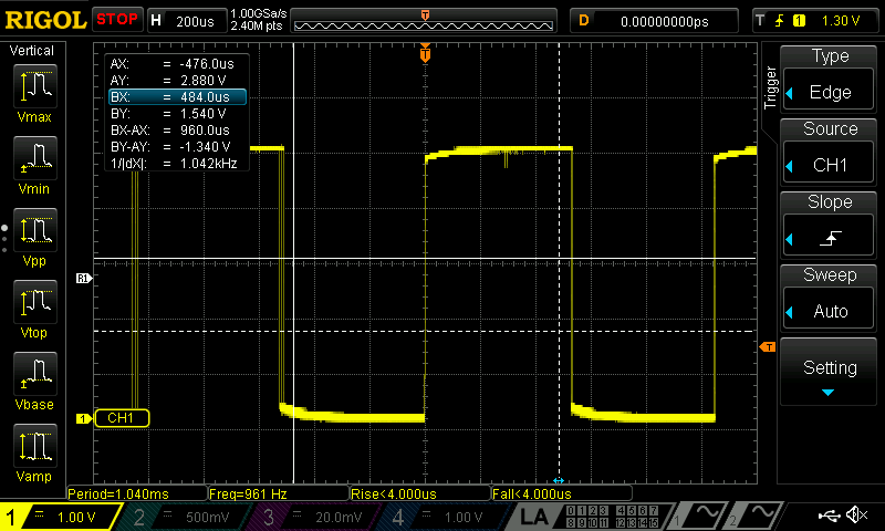 (Figure 3: Oscilloscope trace of a GPIO pin)
Figure 3 shows each interrupt and the main loop that is executed. Here the period is 1.040 ms, so plugging into the equation above, I get a true motor speed of 2.36 rps at 10 V. This is similar to my measured speed which is around 2.4 rps at 10 V.
Results and Discussion
Hardware
Accurate speeds were being measured from the motor and displayed in debugging mode at a rate of 2 Hz.
Interrupt vs. Polling at High Speeds
 (Figure 3: Interrupt Oscilloscope Trace)
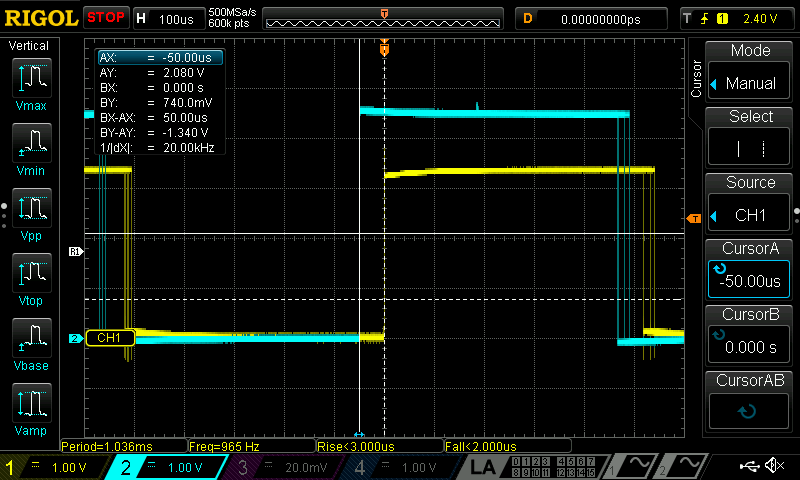
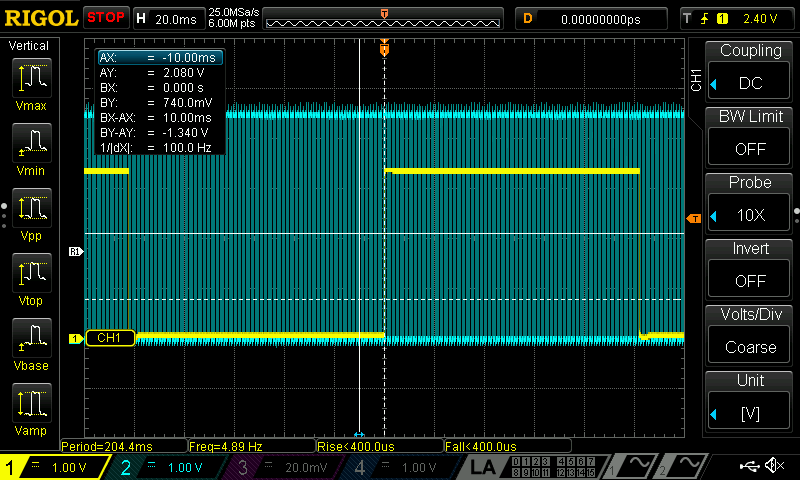 (Figure 4: Polling Oscilloscope Trace)
Figures 3 and 4 compare interrupt based code vs. polling at high speeds. In both traces, the blue signal is an input signal from the motor, and the yellow signal is an output signal from a GPIO pin, which just flips at each edge. In both cases I put a 100 ms delay in the main loop. Figure 3 shows that the interrupts can register inputs and then output something with minimal delay. However, Figure 4 shows the polling method where the output trace (in yellow is heavily aliased). This is because the polling method requires waiting the full 100 ms everytime which is much slower than the input frequency. On the other hand, the interrupt bypasses this. This supports the fact that if the polling period is T, then the average interface latency would be T/2, or at worst T Chapter 12: Interrupts. On the other hand, interrupts have much smaller latency.
Conclusion
This design sucessfully used two interrupts to read from a quadrature encoder and measure and record the speed and direction in which a motor is spinning. I spent a total of 10 hours on this lab.
AI Prototype Summary
For the following AI Prototype, I will be using ChatGPT.
Prompt
Write me interrupt handlers to interface with a quadrature encoder. I’m using the STM32L432KC, what pins should I connect the encoder to in order to allow it to easily trigger the interrupts?
Response
According to ChatGPT, I should use pins STM32 HAL is easier. In this method, each edge (rising or falling) is triggered, the ISR reads A and B to determine direction, and encoder updates its count accordingly.
Generated Code
The code generated for these prompts can be found here.
Reflection
I think the quality of the output was not great. I think at a high-level, the LLM understood what to do, but from what I could tell, the implementation was not quite there. First, it used the hardware abstraction layer STM32 HAL, which is reasonable, but I didn’t understand what it was untill I asked. The LLM generated code that was different than mine. It used STM32 HAL, different pins, and included all code in one file. For some reason, the LLM suggested a polling type method using timers, but I think this is just a hallucination because using polling will cause some latency. Overall, I think the LLM does work better as a sounding board as opposed to just generating code, because it often has bugs in the code it generates.